IOL Guidance
Discover our IOL Guidance System—your solution for precise and efficient implantation of toric IOLs. Using computer-aided technology, it offers intraoperative axis determination and guidance as well as various visual guidance options. Easy to retrofit, patient-friendly, and cost-effective – for workflow optimization in cataract surgery.

Looking for a Partnership!
We are looking for a reliable partner for the completion and distribution of our patented surgical guidance system for implanting toric IOLs.
Feel free to contact us to learn more about our IOL Guidance solution. Visit us for a practical demonstration and see the advantages for yourself.
Key Features and Benefits
Retrofitting Options
This approach is particularly attractive as all microscopes can be retrofitted with a visualization and measurement unit. This eliminates the need to purchase a new and costly guidance system, which is often tied to specific objective brands or associated with a usage fee.
Various Visual Guidance Options
Depending on the surgeon’s preferences, needs and existing equipment, visualization of the toric target axis orientation can be realized in different ways. If a practice or clinic already has a microscope with an image overlay unit, the embedded Option C is the preferred method.
Reliable and Time-saving
No Limitation of the Working Area
The CHRONOS VISION system causes no inconvenience, is easy to use and requires no training time.
Patented Technology
The described guidance technology for implanting toric IOLs from CHRONOS VISION is patent-protected.
Patient-Friendly and Easy to Use
The CHRONOS VISION system causes no discomfort, is easy to use and requires no training period.
Cost-effective
The fact that no special diagnostic device is required for a reference image makes the system considerably more cost-effective than other systems on the market.
Nomination for Innovation Award
CHRONOS VISION Technology
To overcome the aforementioned issues, the toric IOL guidance solution from CHRONOS VISION bypasses the use of diagnostic images and instead performs a new intraoperative measurement of the astigmatism axis while the patient is in the surgical position.
Intraoperative Measurement
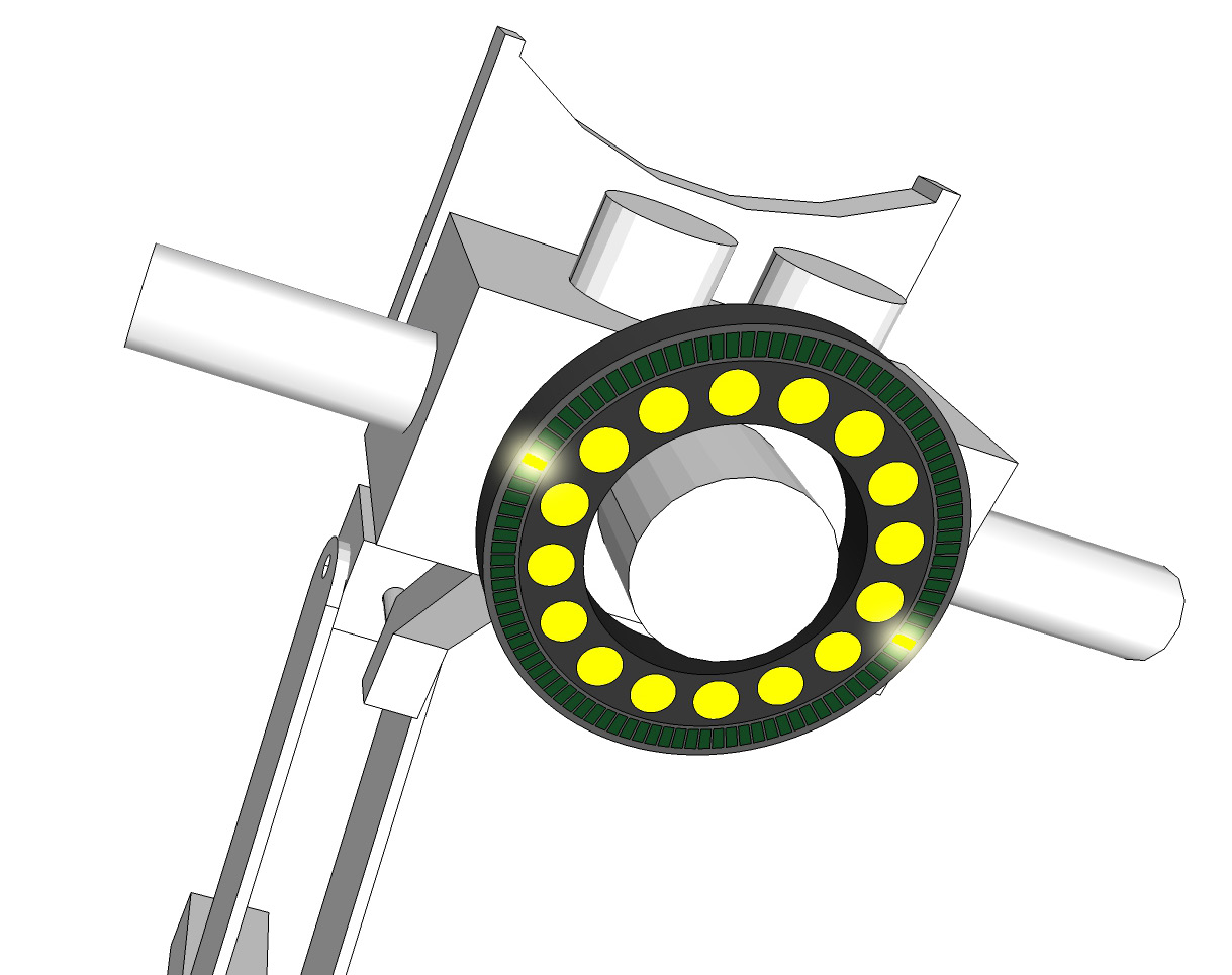
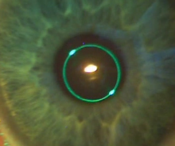
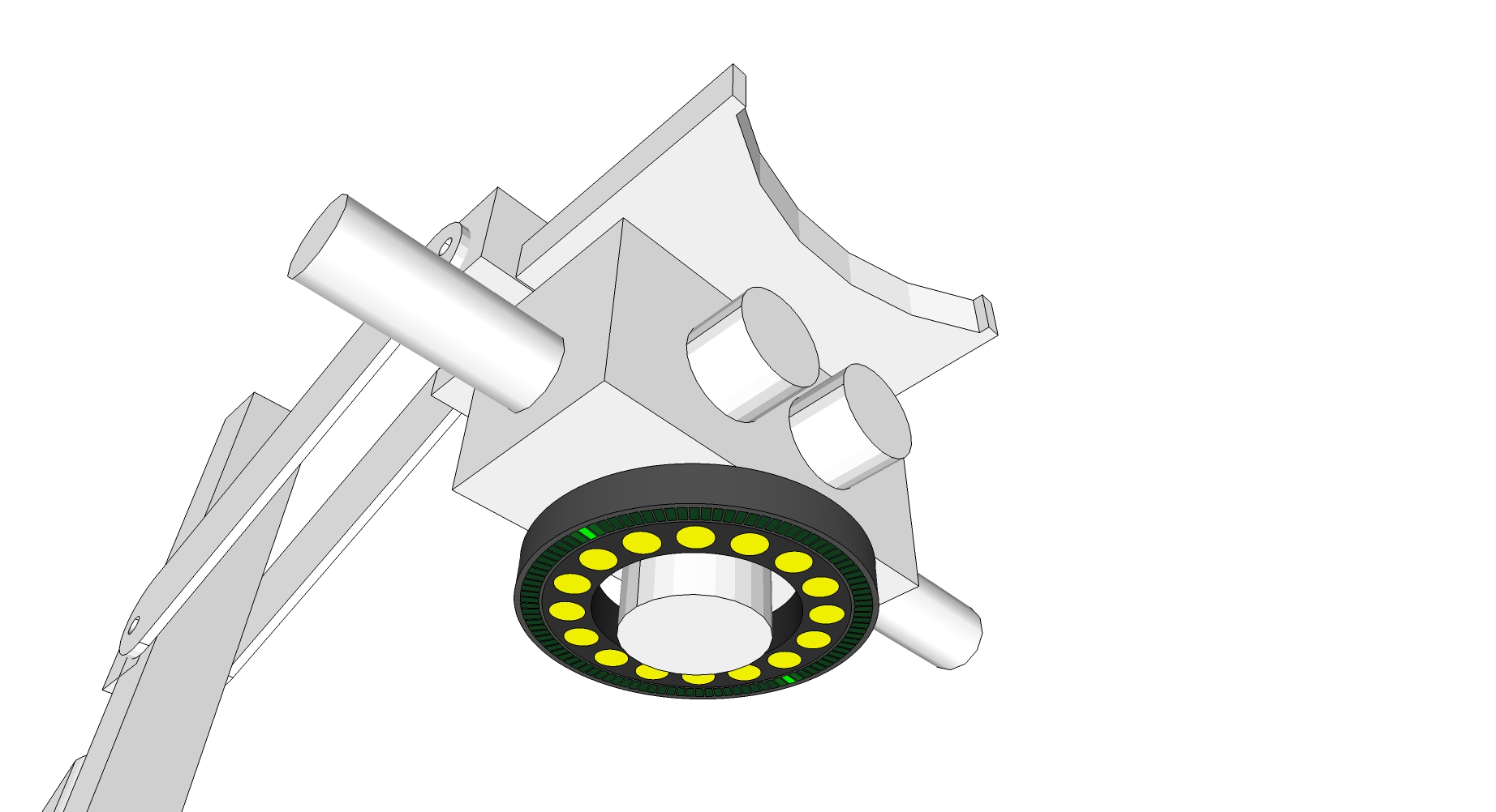
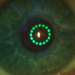
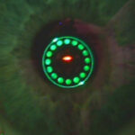
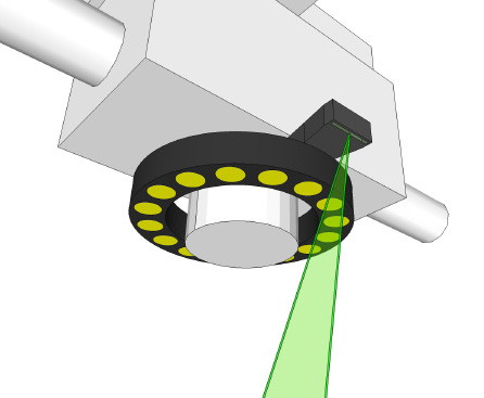
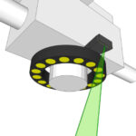
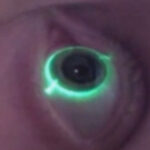
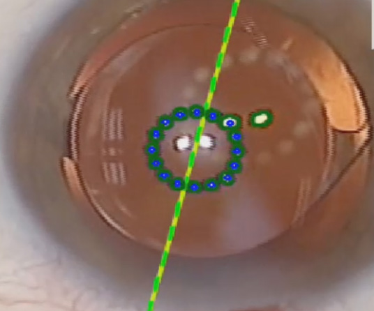
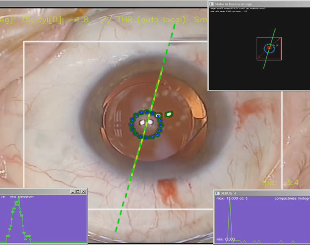
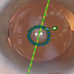
The measurement principle is the same as for diagnosis, i.e. a ring of light sources (measurement ring) placed around the microscope objective is used to generate corneal reflexes that can be observed with the microscope camera. Image processing algorithms localize these reflections in the camera image and infer the actual alignment of the astigmatism axis in real time from the elliptical shape of their arrangement.


Integration and Guidance Options
The CHRONOS VISION system provides various options for the surgeon to depict the actual axis of astigmatism:
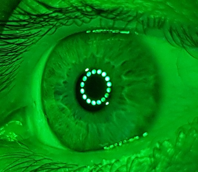
A - Reflection Ring
One of the methods for displaying the measured astigmatism axis values is based on reflection. Here, an additional concentric LED ring creates corneal reflexes, whose virtual connecting line specifies the target orientation of the toric IOL.

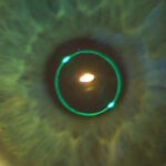
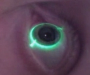
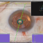
B - Projection onto the Eye Surface
Another option is to project the patient’s astigmatism axis as a luminous line onto the ocular surface. Eye tracking algorithms ensure the luminous line always appears centered relative to the limbus. Various overlays, such as incision guides, can also be displayed.
C - Injection into Viewing Field or external Display
If the microscope is equipped with an image injection module, the axis of astigmatism measured intraoperatively, the desired IOL orientation and any other relevant information can be virtually embedded into the surgeon’s viewing area. Alternatively, all this relevant information can be displayed on an external display to assist with IOL alignment.
Medical Background
Patients suffering from cataracts often require an operation where the natural lens is replaced by an artificial lens implant. About 30% of these patients also have astigmatism, a type of visual impairment. Previously, these patients could only receive spherical intraocular lenses (IOLs), which were not optimized for astigmatism.
Thanks to advances in IOL manufacturing, toric IOLs are now available. These lenses take into account the toric shape of the cornea to correct astigmatism. Precise alignment of the toric IOL axis with the corneal astigmatism axis is crucial for optimal outcomes. Every degree of deviation between axes can reduce the result by 3%.
Motivation and Challenges
During surgery, the question arises as to how the astigmatism axis is aligned compared to the time of diagnosis, since additional rotations of the head and eye may have occurred between diagnosis and surgery. This rotation must be considered to correctly adjust the toric IOL axis. Most surgeons use a manual technique to mark the desired orientation of the lens. Modern systems attempt to solve this problem using image processing, by determining the torsion between current and diagnostic images of a microscope camera.
Inaccurate manual
Marking Methods
In many practices, reference and astigmatism axes are still marked manually with stamps and pens to guide the toric IOL correctly. The quality of these marks is crucial for the surgical outcome, as inaccuracies such as marks that are too thick, poor patient cooperation, and smudging or fading ink can occur. Each degree of axis deviation reduces effectiveness by 3%. With typical errors of 5°, this means a loss of effect of 15%.
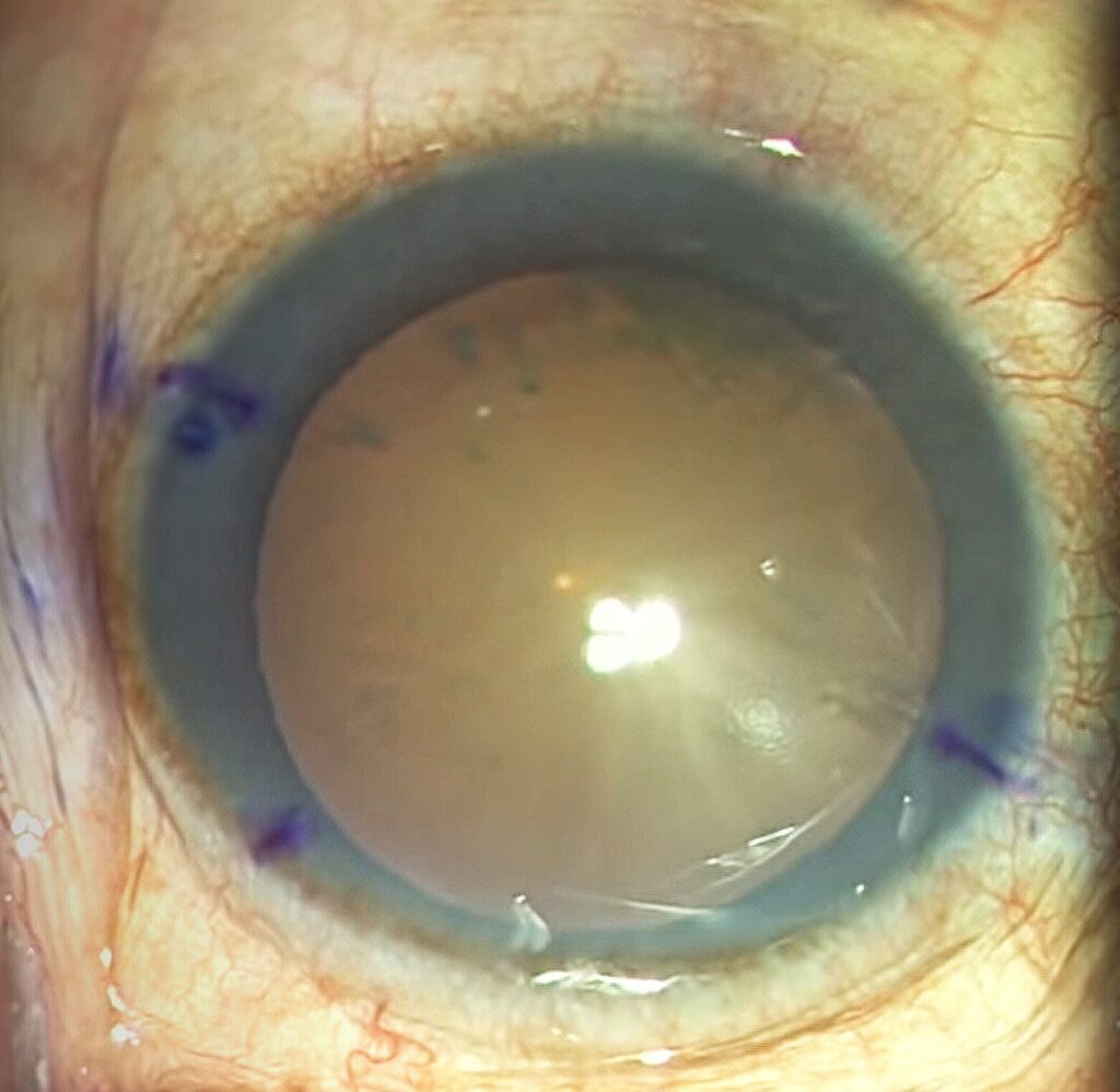
Lack of Blood Vessels
The image illustrates the potential problem that during surgery there may not be enough corresponding scleral or limbal vessel features available for image-guided alignment. While the diagnostic image shows clear features, few vessels may be found during surgery, for example due to conjunctival chemosis. Moreover, regions that displayed pronounced scleral vessels during diagnosis may not be visible during the operation because of the microscope camera’s orientation or a limited field of view.
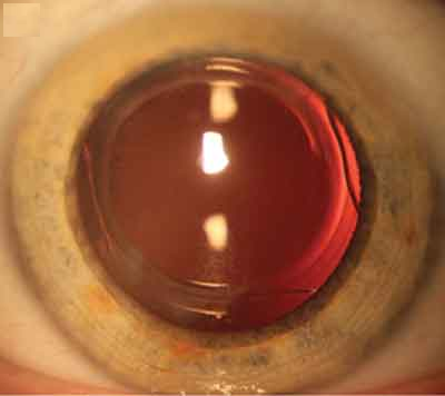
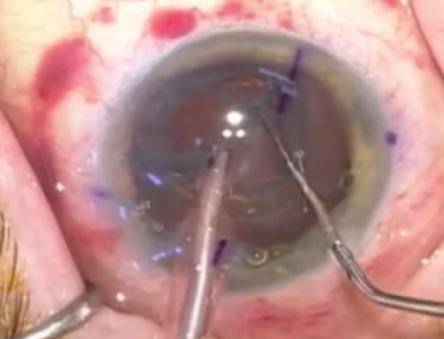
Hematomas
During lens fragmentation with a femtosecond laser, the eyeball must be stabilized to prevent movement. This can lead to scleral hematomas, partially covering the scleral vessels. As a result, the registration process in which the image processing algorithms calculate torsion may fail.